Rv Trailer Battery Wiring Diagram
It reveals the parts of the circuit as streamlined shapes, as well as the power and also signal links in between the gadgets. We recommend these standards because they are pretty universal.
 Rv Battery Wiring Diagram Trailer wiring diagram
Below is a rv electric wiring diagram or schematic including the converter and inverter for a generic rv.

Rv trailer battery wiring diagram. 7 pin trailer wiring diagram; Batteries, i opted to set up my rv solar power system with 2 battery banks — individually charged through 2 separate charge controllers. As the rv battery disconnect switch cuts off your battery from the rest of your unit, and no part of the rv can draw power from the battery, it protects against dangers such as electrical fires and theft.
Fb 8637 battery wiring diagram trailer 12 volt parallel explained hc 4564 for rv 12v batteries in schematic 1 disconnect switch travel wrg 3124 camper inverter install four diffe diy methods to get off the grid lh 4567 solar panels caravan free 6a3 mandalay motorhome library sunseeker box is this a lithium scheme correct fb 8637 battery wiring… read more » That said, for specific situations, there are industrial standards with different connectors and wire arrangements. Gmc acadia with tow package · will camper battery connected to truck trailer connector drain truck battery.
7 way plug wiring diagram standard wiring* post purpose wire color tm park light green (+) battery feed black rt right turn/brake light brown lt left turn/brake light red s trailer electric brakes blue gd ground white a accessory yellow this is the most common (standard) wiring scheme for rv plugs and the one used by major auto manufacturers today. The negative lead of the trailer is connected to the the negative lead of the first battery. Use the rv electrical diagram we made below to get an understanding of what powers what and to learn how an rv electrical system works.
When wiring a trailer connector, it is best to wire by function, as wire colors can vary. The zamp 30 amp digital dual battery bank solar controller is different because it can charge and maintain two different battery banks at once! Do i disconnect the negative cable that goes from my trailer frame to my battery and connect it to one post on the switch, then take another cable, connect.
That goes into building every aliner camper. Beyond protecting your rv from the dangers of unregulated power, the fuse board will also act as a distribution panel, splitting the power drawn from the coach battery down into smaller wires which serve separate entities, such as individual appliances or circuits for lighting or outlets. Back up purple 16 back up of vehicle's wiring.
So we attempted to uncover some terrific rv inverter wiring diagram graphic to. Collection of travel trailer wiring schematic. Honestly, we also have been remarked that rv inverter wiring diagram is being just about the most popular field at this moment.
If your rv is a motorhome, your exterior lights operate on your engine battery. This car is designed not just to travel one place to another but also to take heavy loads. Just to be clear, we are talking.
The trailer positive lead should be connected with the first battery’s positive terminal. Dual rv battery wiring diagram dual rv battery wiring diagram inside rv inverter wiring diagram, image size 771 x 770 px, and to view image details please click the image. It’s also important to shut off the power as a safety measure when you’re doing maintenance.
Duoetto 12 volt 10 litre water heater draws 22 amps (that's 22 amps per hour) on 12 volt and is 4 metres from the battery. A wiring diagram is a streamlined traditional photographic depiction of an electric circuit. With that being said, here are some great explanation videos to help you get a better feeling for how all this stuff works and why
This connection will help maintain the batteries when the vehicle is running, but will not charge them sufficiently from a discharged state. Rv battery disconnect switch wiring diagram best battery isolator. If not, the arrangement will not function as it ought to be.
Cable capacity at 12.6 volt to a maximum loss of 5%. Search for r vision rv wiring diagrams here and subscribe to this site r vision rv wiring diagrams read more!. Rv solar wiring diagram zamp solar roof mounted solar kits zamp 30 amp digital dual battery bank solar controller.
If you are looking at the inside of the trailer connector where the wires mount to the terminals starting at the top and rotating clockwise: Battery lead break away kit, interior lights and battery charger. The following trailer wiring diagram(s) and explanations are a cross between an electrical schematic and wiring on a trailer.
Then connect the two positive posts together with charger wire, secure the clamps, and then do the same with the negative posts. Sure power battery isolator wiring diagram fresh thesamba type 2. We have an excellent wiring diagram on our website, i will provide you a link so you can look at it.
Rv wiring for dummies is a great page with several different videos to help you understand rv electricity. But if your rv is a trailer, they operate on your coach battery. That’s adequate to run most systems of the stock rv for a day or two.
It is often found on newer trucks and suvs that come equipped from the factory with a trailer hitch. Wiring tips for your rv solar power system. Wiring diagram isolator switch new wiring diagram alternator to.
Annually inspect the wires under the trailer and on the axle for broken insulation or. 2000 dodge dakota ignition wiring diagram, 2000 dodge dakota pcm wiring diagram, 2000 dodge dakota trailer wiring diagram, 2000 dodge dakota wiring diagram, 2000 dodge dakota. Rv electrical diagram (wiring schematic) understanding you campers electrical wiring can be very confusing.
Heartland rv wiring schematics ~ you are welcome to our site, this is images about heartland rv wiring schematics posted by maria rodriquez in heartland category on oct 30, you can also find other images like wiring diagram, parts diagram, replacement parts, electrical diagram, repair manuals, engine diagram, engine scheme, wiring harness, fuse. It requires a cable of at least 8mm² or 8 b&s. With the dual settings you can set the controller to charge each battery bank at a different rate.
So, as you probably know, your interior lights operate on your coach battery voltage, the same as with your temperature control panel and your fridge control panel. Each component ought to be set and connected with different parts in particular manner.
 Australian Land Rover Owners Electrical plug wiring
 Battery will have the breaker mounted on the batteryside
 Bring Your Van Camper to Life How to Add Batteries and a
 How To Wire 12 Volt LED Lights In Your Camper Van
 Mortons on the Move 24V Tesla Battery Module Wiring
 Complete 12v Campervan, RV, MotorHome, Boat Wiring
 12V/ 240V Camper Wiring Diagram T5 Interior Pinterest
 Nasa Battery Monitor Wiring Diagram
 Project Solar and Battery bank addition for an RV RV
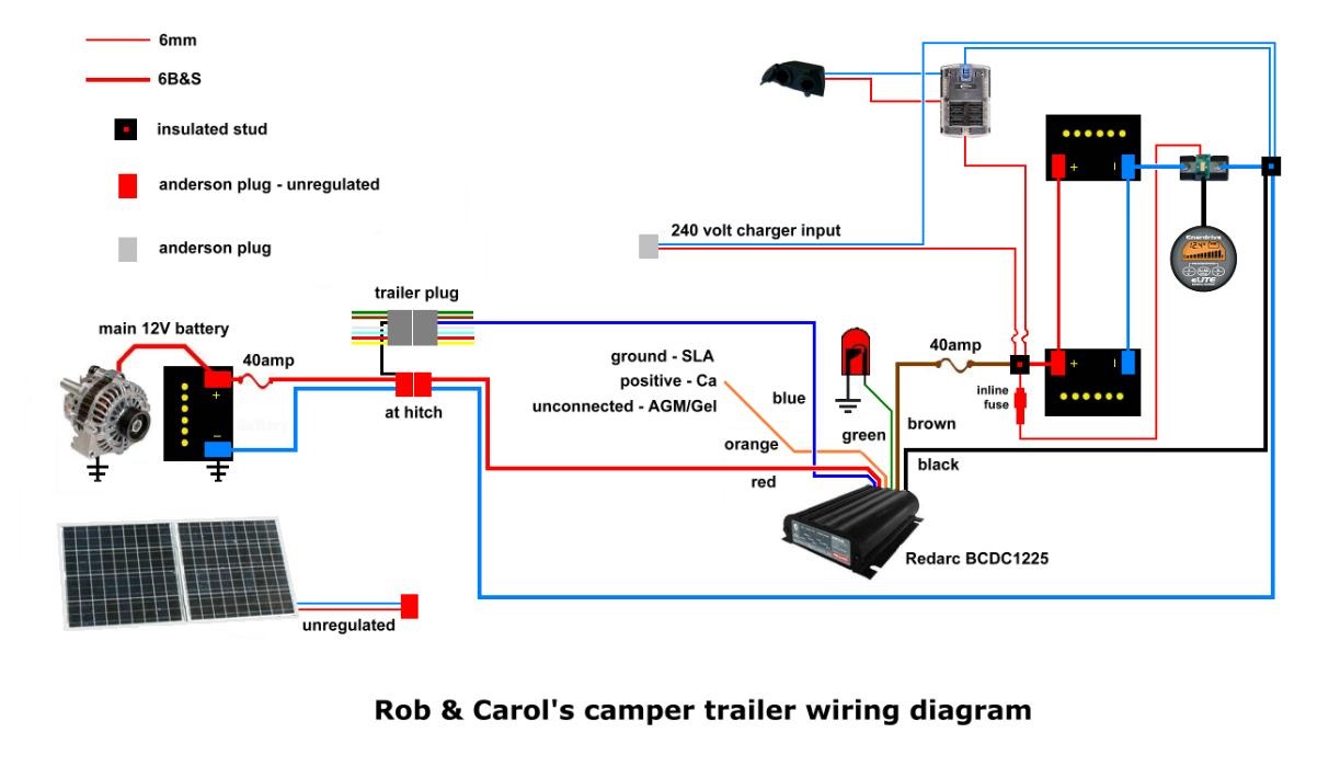
Camper trailer 12v setup Teardrop trailer plans, Camper
 Pin on Alt in Ergy
 RV POWER UPGRADE Live Breathe Move Beautiful Wiring
 RV Inverter Wiring Diagram RV Inverter Wiring Diagram
 Xantrex mobile inverter installation diagram for a typical
 Camper Trailer Battery Wiring Diagram
 Hi all,I have a camper trailer and I want to wire it for
 Rv Converter Wiring Diagram In Camper Plug Battery Images
 Draft of RV Electrical Systems … Rv solar system, Rv solar