Solenoid Electrical Schematic Symbol
A wiring diagram is a streamlined standard pictorial representation of an electrical circuit. When dealing with a large power distribution system, a special type of schematic diagram called an electrical single line is used to show all or part of the system.
 Honda Wiring Diagram Symbols Component Symbol For Ground
This article gives some of the frequently used symbols for drawing the circuits.

Solenoid electrical schematic symbol. Download these electrical schematic symbols cad collection in dwg format. The solenoid valve is an electromechanical valve that is used to regulate the flow of any liquid or switch the flow of liquid into other ports. These are mostly we used for draw circuit diagrams.
Figure 11 wiring diagram of a car’s electrical circuit. See more ideas about electrical schematic symbols, electrical symbols, electrical wiring diagram. The relay / electromagnetic switching devices controls are activated by signals.
Pneumatic symbols only when the design fails does it draw attention to itself; Understanding ansi / iso schematic symbols for fluid power and pneumatic components are used to identify and graphically denote the function and operation of piped control systems. Recognizing and understanding schematic symbols will enable you to comprehend a circuit’s function.
Assortment of solenoid valve wiring schematic. Solenoid valve and other pneumatic system common symbols. It reveals the parts of the circuit as streamlined forms, and the power as well as signal links between the devices.
A wiring diagram is a streamlined traditional pictorial representation of an electric circuit. Most of the time, a small voltage or current is used to switch other voltages or higher currents may be electromechanical or fully electronic type. They are mostly used to draw a circuit diagram and are standardized internationally by the ieee standard (ieee std 315) and the british standard (bs 3939).
Each electrical component may have numerous representations as the electrical symbols can vary from country to country nowadays. 4 ports 2 positions 4/3 valve. The advantage of an electromagnet over natural magnet is that it can be turned on or off when required by energising the coil.
There are different type of solenoid valves depending on current and its mechanism. Some electrical symbols become virtually extinct with the development of new technologies. Variety of 12 volt solenoid wiring diagram.
Solenoid valve and common pneumatic system symbols. The relay are switching devices activated by signals. These wiring diagram symbols include;
Schematic symbols are used to identify and graphically depict the function of fluid power components. A significant voltage drop between the power supply and solenoid may occur if there is unexpected resistance, such as long lead wires or other electrical components. When it succeeds, it’s invisible.
Most of the time, a small voltage or current is used to switch other voltages or higher currents that may be electromechanical or fully electronic type. In electronic circuits, there are many electronic symbols that are used to represent or identify a basic electronic or electrical device. A solenoid is a device that converts electrical energy into mechanical energy.
And how they relate to solenoid valves and pneumatic equipment. Solenoid valves symbols for use in electrical, pneumatic and hydraulic schematic diagrams. There are many electrical and electronic schematic symbols are used to signify basic electronic or electrical device.
Berry all the symbols you need to design your pneumatic circuit in.dxf format. Inductor symbols / coils / chokes. The inductors or coils are passive components that have a certain number of turns of wire that introduce magnetic inductance to an electrical circuit to produce a magnetic flux or to mechanically react to magnetic flux variations.
Figure 12 schematic of a car’s electrical circuit. Available in svg, png, jpg, dxf & dwg formats What is a solenoid and how does it work?
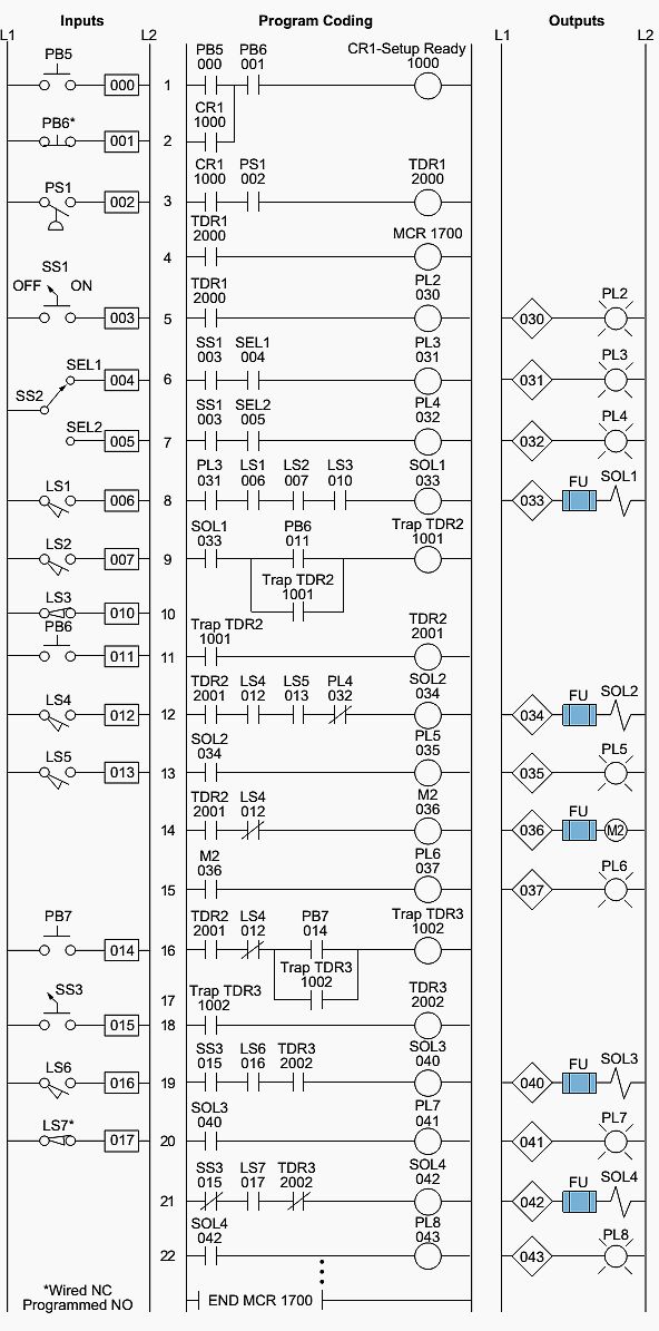
There are some standard symbols to represent the components in a circuits. Schematic drawings document the machine logic only and are never to be used as a piping diagram. Let's take a look at how to use the basic electrical symbols to draw a schematic diagram of the circuit and its components.
In cases where there is more than one universal electrical symbol, we have tried to give an alternate representation. It reveals the elements of the circuit as simplified forms, as well as the power as well as signal connections between the devices. Switches , batteries , grounds , resistors , diodes , transformers , capacitors, transistors , inductors, connectors , relays and many more schematic dwg cad symbols.
Figure 10 comparison of an electrical schematic and a wiring diagram.
 Beautiful 12 Volt Relay Wiring Diagram Symbols diagrams
 Schematic Symbols Chart Wiring Diargram Schematic
 circuit schematic symbols circuit diagrams symbols
 Hydraulic Solenoid Valve Wiring Diagram volovets.info in
 The 21 Best Wiring Diagram Creator Circuit diagram, Diagram
 Beautiful 12 Volt Relay Wiring Diagram Symbols diagrams
 Circuit symbols Electrical circuit diagram, Electrical
 Wiring Diagram Electrical. Wiring Diagram Electrical
 File0002.jpg (960×1600) Electrical circuit diagram
 pnuematics symbols John Deere Electrical Symbols
 Beautiful 12 Volt Relay Wiring Diagram Symbols diagrams
 ComponentWiring Schematic Symbols And Meanings Electrical
 17 Auto Wiring Diagram Symbols Legend Ideas bacamajalah
 Unique Fan Relay Wiring Diagram Hvac diagram
 12 Volt Relay Wiring Diagram Symbols Electrical symbols
 motherboard symbols Google Search Electrical symbols


